Creating a redundant network
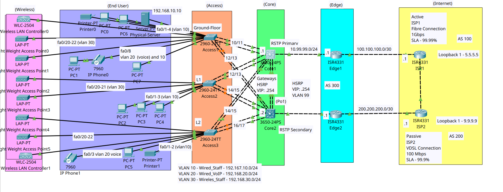
The goal of this post is to document the design decisions, the configurations, and the networking concepts that were applied throughout the lab. It was a useful way to reinforce topics like redundancy, VLAN segmentation, HSRP, BGP, NAT, and routing in a realistic Packet Tracer environment.
Lab objective
The objective of this lab is to build a fully redundant enterprise network in Packet Tracer, starting from the internet edge and working inward through the edge, core, access, wireless, and end-user layers. The design includes dual ISP connections, redundant edge routers with HSRP, redundant core switches, access-layer VLAN segmentation, wireless connectivity, DHCP, routing, and NAT so the network can stay available even if a device or link fails.
This lab was designed to show how the different layers of an enterprise network fit together and how redundancy is built into each part of the topology. By the end, the network is able to provide connectivity from end-user devices all the way out to the internet while keeping the design resilient, organized, and scalable.
Disclaimer: This lab was completed by following Dan Miller’s Cisco Packet Tracer Lab Mastery: Build and Secure Advanced Topologies. (https://www.packtpub.com/en-us/product/cisco-packet-tracer-lab-mastery-build-and-secure-advanced-topologies-9781806708390) I used it as a guided learning exercise, taking notes and making sure I understood each concept as I built the topology. This post is my documentation of that learning process.
Internet side
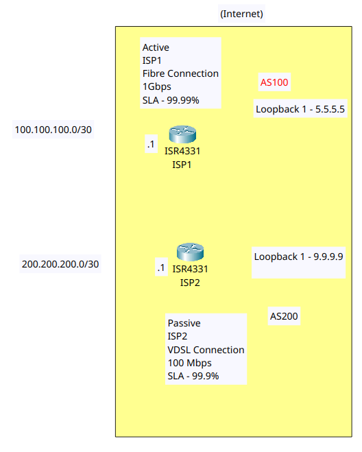
This part of the lab introduces a true redundant internet design using two separate ISP routers. The goal was to create a setup that can continue operating if the primary internet connection fails.
I treated ISP1 as the active path, using a fiber link with 1 Gbps bandwidth and a 99.99% SLA, while ISP2 served as the passive backup with a VDSL link, 100 Mbps bandwidth, and a 99.9% SLA. Each ISP was also given a loopback address to represent internet reachability in the lab.
The key idea behind this design is that redundancy means more than simply having two links. It requires two independent providers and two separate paths, so a failure in one does not affect the other. That is why I avoided a setup where both links depended on the same infrastructure.
To make the design realistic, I used BGP with separate autonomous systems so the routers could exchange routes the way real ISPs do. This reflects how enterprise networks connect to external providers and choose the best available path.
Edge design
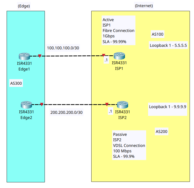
I added two edge routers to eliminate the single point of failure at the network edge. The goal was to ensure the LAN could still reach the internet even if one router failed or needed maintenance.
While a single edge router is simpler, it also creates a major outage risk if that device goes down. With two edge routers, traffic can continue flowing through the second router during hardware failures, software issues, or planned upgrades.
To support seamless failover, I used HSRP so both routers could present a single virtual default gateway to internal devices. This allows users to keep sending traffic to the same gateway IP while one router remains active and the other stands by ready to take over.
This part of the lab reinforces an important lesson: redundancy has to exist at multiple layers. Protecting against ISP failure is not enough if the edge itself is still a single point of failure.
Core design
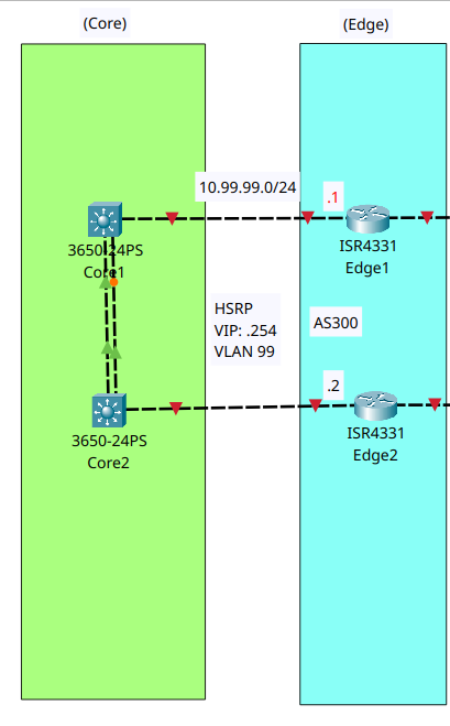
I added two core switches to eliminate the network’s dependence on a single switching device. The goal was to keep the core fast, simple, and resilient, while still allowing traffic to continue flowing if one switch failed.
A single core switch would create a major single point of failure. By using two core switches, I introduced redundancy, improved uptime, and left room for future expansion without having to redesign the network.
I used a collapsed-core approach, which keeps the design simpler by combining core and distribution functions. I also connected the edge routers through VLAN 99 so they could exchange HSRP traffic and use the shared virtual gateway address of 10.99.99.254.
The inter-core link was included so the two switches could operate together, and the blocked spanning-tree port was expected at this stage because the port-channel had not yet been configured. At this point in the lab, the focus was on building the structure before moving into the detailed configuration.
Access design
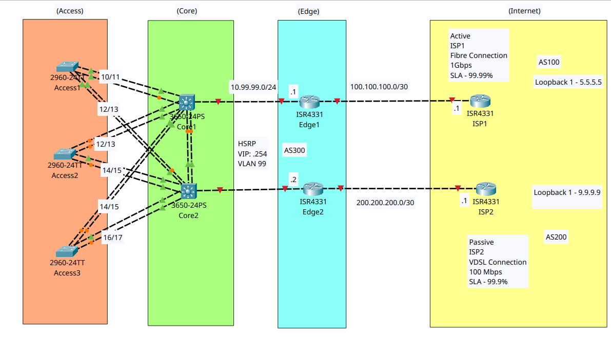
I added three access switches to connect end devices to the network and keep user access resilient. This layer is where the network reaches PCs, phones, printers, and access points, so I wanted it to remain flexible and fault tolerant.
If a single access switch fails, everyone connected to it loses service, so each access switch was given redundant uplinks to both core switches. That way, traffic can still reach the network even if one uplink or one core switch goes down.
I focused on the user experience here, because downtime at the access layer is immediately visible to the people using the network. I also wanted this design to support VLANs, access control, and future authentication policies such as 802.1X, even though those configurations come later.
I kept the access layer separate from the core instead of connecting the access switches directly to one another, because user traffic should pass through the core. The multiple uplinks also prepare the design for spanning tree and port-channel behavior later in the lab.
End-user design
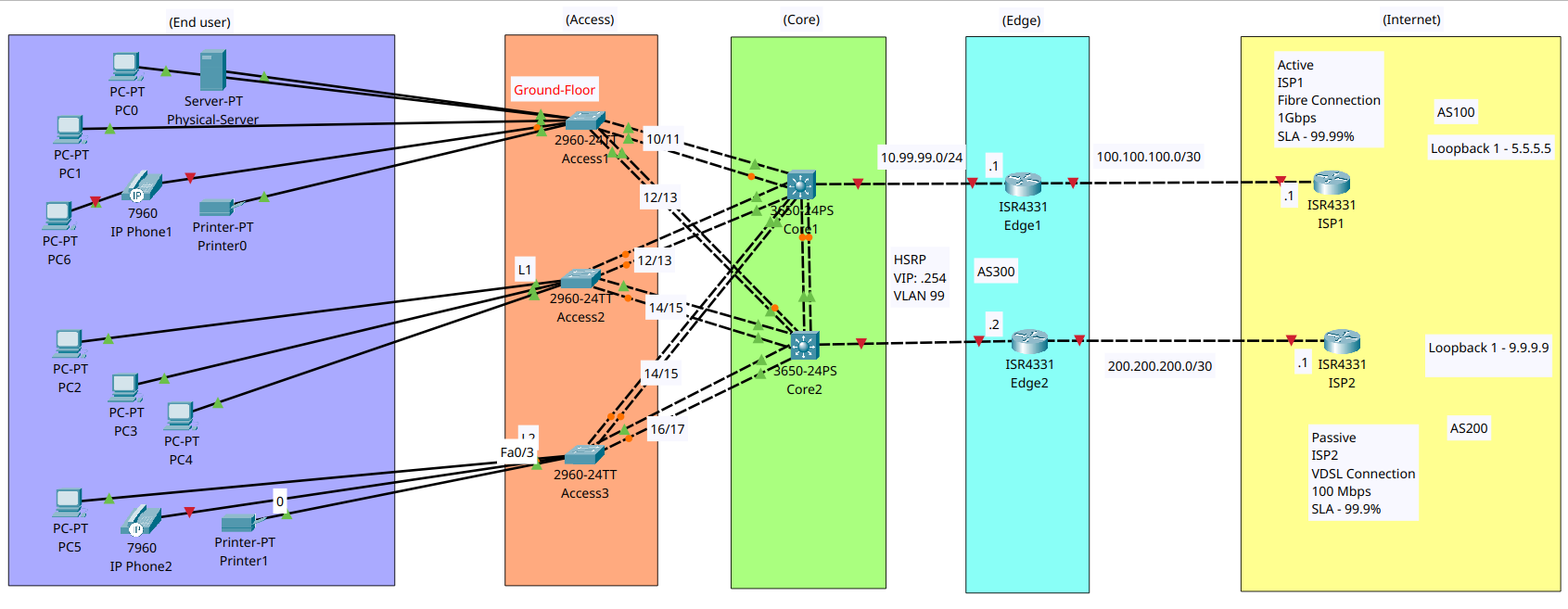
I added the end-user layer to show where the network is actually used by people and devices. This included PCs, IP phones, printers, servers, and wireless endpoints that rely on the access layer to reach the rest of the network.
I focused on the user experience here, because this is the layer where the network has to support real people and their daily tasks. The goal was to show that the design is not just about routers and switches, but also about providing reliable access to applications, printing, voice, and internal services.
I distributed the devices across different floors to make the access design feel more realistic and to show how end users connect through nearby access switches. I also used a mix of wired connections and a phone-with-PC passthrough setup to reflect how office networks often handle voice and data at the same desk.
End users do not usually need the same level of redundancy as the core or edge, but their connections still need to be stable and organized. The purpose of this layer is to make the network usable, secure, and easy to segment with tools such as VLANs and access controls.
Wireless Design
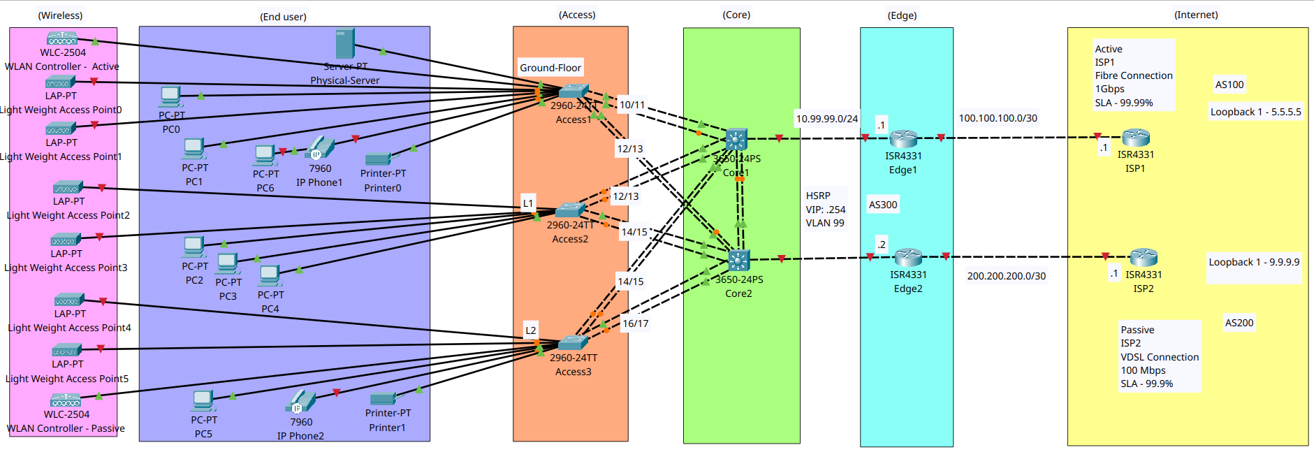
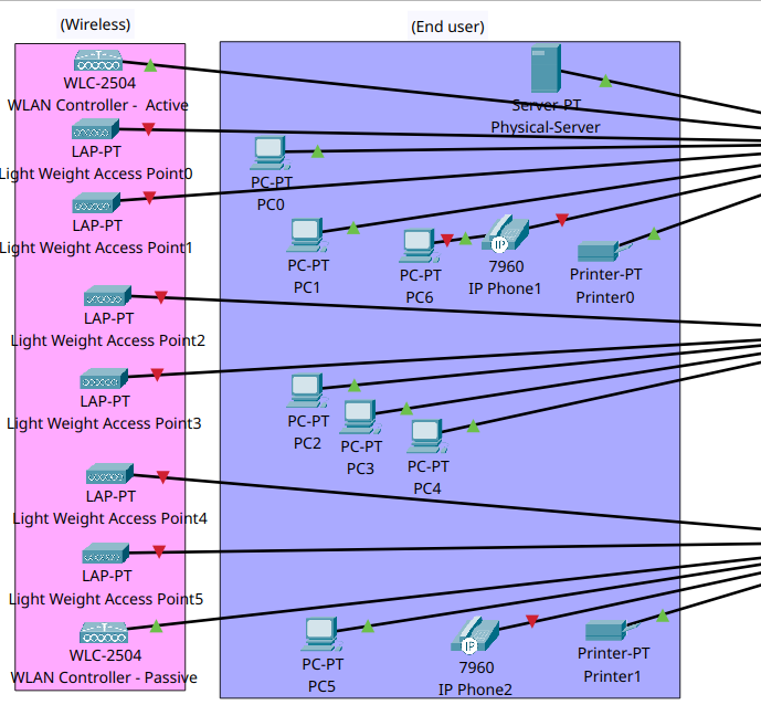
I added a wireless layer with a WLC and lightweight access points to show how Wi‑Fi fits into the overall network. This kept wireless as its own design layer while still treating it as part of the end-user environment.
Because the WLC acts as the control plane for the wireless network, I treated it as a potential single point of failure and modeled an active-passive setup. I also placed the devices on different floors to account for switch failure and improve resilience.
For coverage, I used overlapping access points so users could stay connected even if one AP failed or went offline. The idea was to make sure the wireless network still had a path forward with minimal impact on users.
Packet Tracer has limits when it comes to realistic wireless behavior, so this section was focused more on the design concept than on fully configuring every wireless feature. The main goal was to understand how a real Wi‑Fi deployment should be structured before moving on to IP planning.
VLAN Design
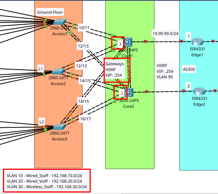
I split the internal LAN into three VLANs: VLAN 10 for wired staff, VLAN 20 for wired voice, and VLAN 30 for wireless staff. This keeps the network organized and lets each device type live in its own logical segment.
IP plan
I assigned one subnet to each VLAN: 192.168.10.0/24 for wired staff, 192.168.20.0/24 for voice, and 192.168.30.0/24 for wireless staff. I used .1 and .2 for the core switch gateways and .254 as the HSRP virtual IP on each VLAN.
I wanted a simple design that still showed how VLANs separate traffic and how the core provides the default gateway through HSRP. This also gave me a clean foundation for later configuration topics like trunks, access ports, and spanning tree.
This structure makes the LAN easier to manage and keeps voice, wireless, and data traffic separated from each other. It also makes the redundancy design clearer because the core switches act as shared gateways for the internal network.
ISP Configuration
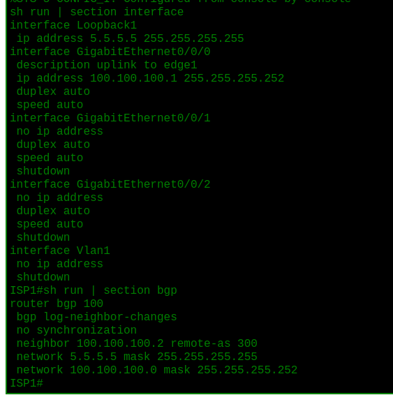
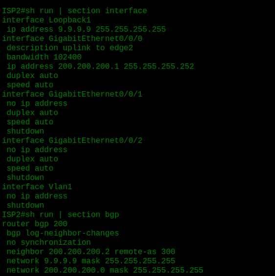
I started with the internet side of the lab so the WAN foundation was in place before moving inward. ISP1 was configured with a loopback, an uplink to Edge1, and BGP AS 100 advertising its loopback and link subnet, while ISP2 was configured in the same way in AS 200 with its own loopback and uplink to Edge2.
BGP was used so each ISP could advertise its own network and exchange routes with the edge routers across separate autonomous systems. This reflects the real-world model of two independent providers feeding a redundant enterprise edge.
Edge configuration
Edge1

Edge2 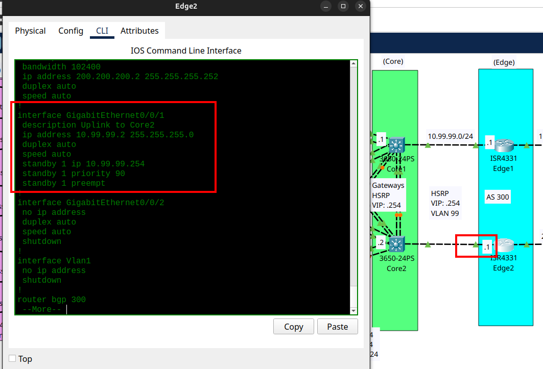
I configured the edge routers so they could communicate with their ISP uplinks and share an internal gateway through HSRP. Edge1 was set as the active router with the higher priority, while Edge2 served as the standby backup.
I wanted to verify outside connectivity first, because there is no point moving inward if the WAN side is not working. I then used VLAN 1 temporarily for the internal edge link so I could confirm the HSRP failover behavior before moving it later to VLAN 99.
This step confirmed that the edge could reach both ISPs and that internal devices could continue using the same virtual gateway if one edge router failed. It also highlights the difference between a physical router IP and the shared HSRP virtual IP.
Verification: 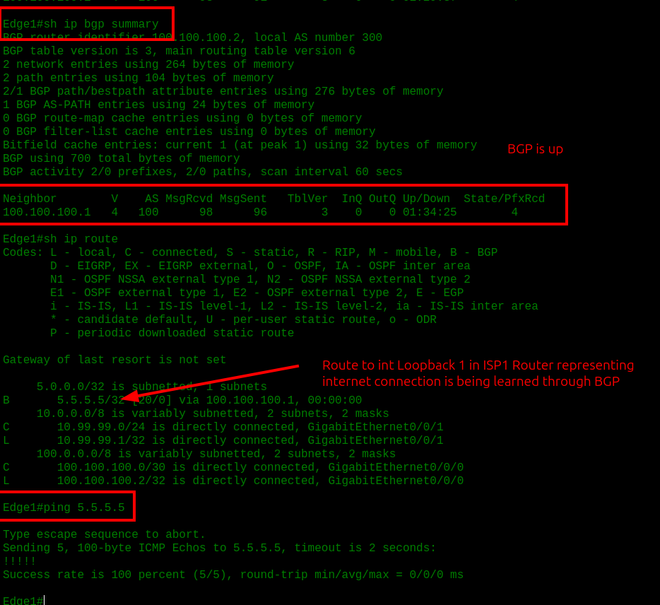
I did same verification on Edge2 Router.
Core setup
Core1
1
2
3
4
5
6
7
8
9
10
11
12
13
14
15
16
17
18
19
20
21
22
23
24
25
26
27
28
29
30
31
32
33
34
35
36
37
38
39
40
41
interface Port-channel1

description Uplink to Core2

switchport trunk native vlan 99

switchport trunk allowed vlan 99

switchport mode trunk

!

interface GigabitEthernet1/0/1

switchport access vlan 99

switchport mode access

!

interface GigabitEthernet1/0/23

switchport trunk native vlan 99

switchport trunk allowed vlan 99

switchport mode trunk

channel-group 1 mode active

!

interface GigabitEthernet1/0/24

switchport trunk native vlan 99

switchport trunk allowed vlan 99

switchport mode trunk

channel-group 1 mode active
For Core2 I applied the same concept of configuration.
I moved the HSRP link off VLAN 1 and onto VLAN 99 so the inter-core communication had its own dedicated management VLAN. I also created a port-channel between the two core switches to carry that traffic with redundancy and extra bandwidth.
The edge routers do not need to know about VLAN 99 directly because the switch assigns that VLAN on the port connecting to the router. In this setup, the router just sends normal Ethernet traffic, while the switch treats that link as part of VLAN 99.
At this point, the idea is to cleanly separate internal user traffic from the router coordination traffic. VLAN 99 gave me a safer design, and the port-channel made the core-to-core link more resilient than a single cable.
Verification 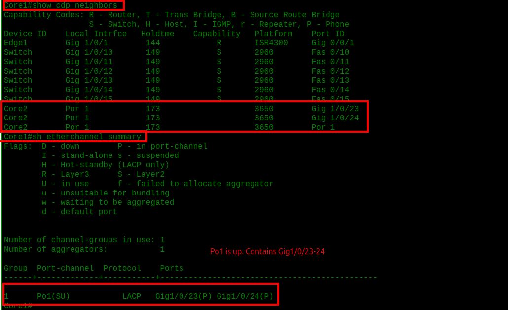
Next, I built the VLANs on both core switches because they act as the gateway for the end-user network. I created VLAN 10 for wired staff, VLAN 20 for wired VoIP, and VLAN 30 for wireless staff, then enabled Layer 3 routing on the switches so they could handle inter-VLAN traffic (with ip routing command .
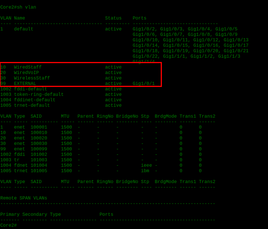
After creating the VLAN database on both core switches, I assigned each VLAN its own gateway IP and configured HSRP so the two cores could share a virtual default gateway. Core1 used the .1 IPs and higher priority values, while Core2 was prepared with the .2 IPs and lower priority so it could take over if needed.
1
2
3
4
5
6
7
8
9
10
11
12
13
14
15
16
17
18
19
20
21
22
23
24
25
26
27
28
29
30
31
32
33
34
35
36
37
38
39
interface Vlan10

ip address 192.168.10.1 255.255.255.0 // .2 in Core2

standby version 2

standby 10 ip 192.168.10.254

standby 10 priority 110 // priority 90 in Core2

standby 10 preempt

!

interface Vlan20

ip address 192.168.20.1 255.255.255.0 // .2 in Core2

standby version 2

standby 20 ip 192.168.20.254

standby 20 priority 110 // priority 90 in Core2

standby 20 preempt

!

interface Vlan30

ip address 192.168.30.1 255.255.255.0 // .2 in Core2

standby version 2

standby 30 ip 192.168.30.254

standby 30 priority 110 // priority 90 in Core2

standby 30 preempt
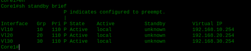
I set up the VLANs on all three access switches first so the access layer was ready before I started assigning ports and connecting it to the core. Each switch got the same VLANs for wired staff, voice, and wireless staff, which kept the access layer consistent across the whole design.
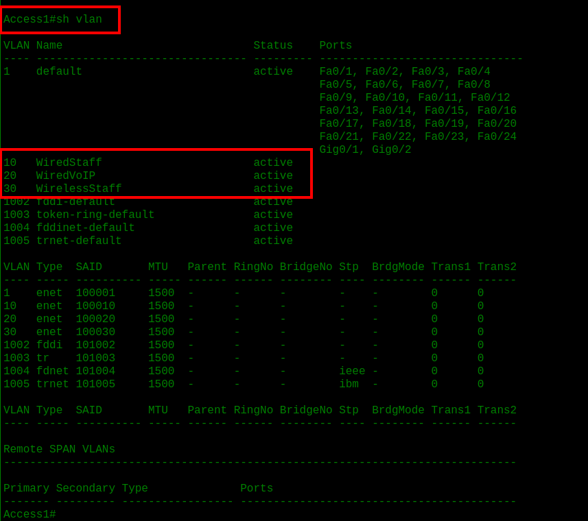
Access Ports
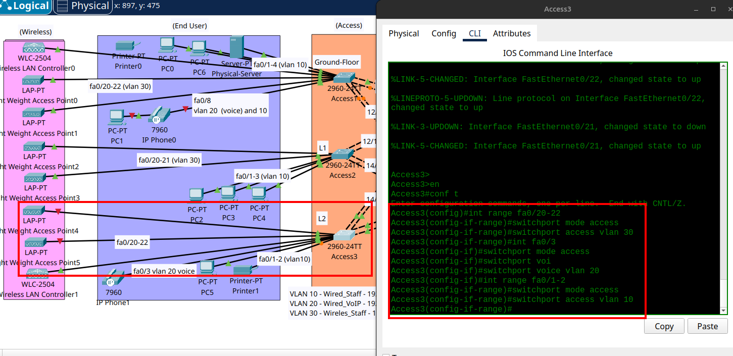
I grouped the end-user devices by floor and assigned each group to the correct VLAN on its access switch. Wired devices went into VLAN 10, IP phones used VLAN 20 for voice, and wireless devices were placed in VLAN 30.
I wanted the access layer to stay organized and efficient, so each device type had a clear role instead of being spread randomly across the switches. For phones, I separated voice and data traffic so the same desk could carry both properly.
This made the access layer ready to connect into the core without confusion and gave each device a clean path through the network. It also set up the lab so the later trunk and port-channel configuration could be tied in more easily.
Core to access
Access3 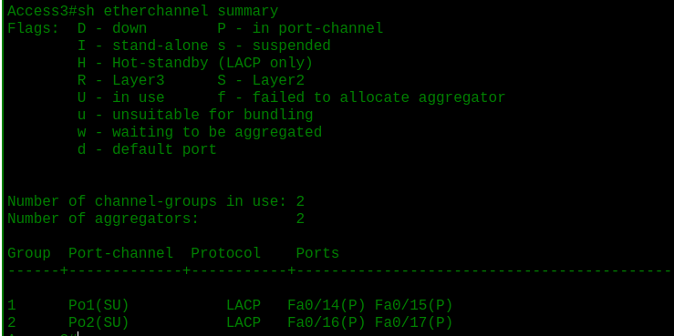 Core1
Core1 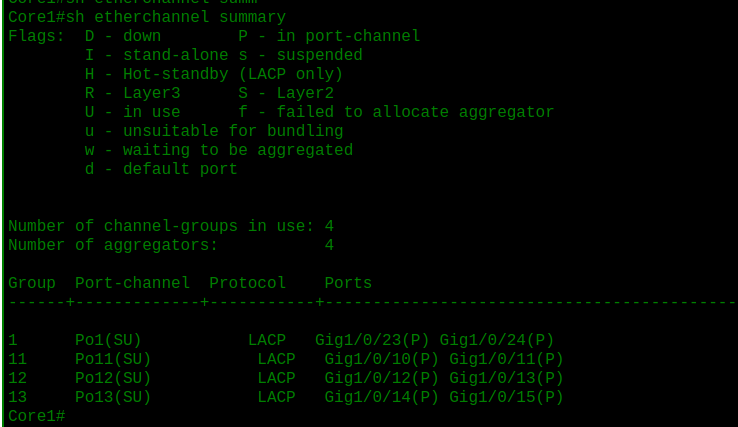
I connected the core and access layers using port-channels and trunk links so the VLANs could actually move between the switches. VLANs 10, 20, and 30 already existed, but this step made them usable across the whole network.
The goal was to bundle the redundant links together and carry the user VLANs with VLAN 10 as the native VLAN.
Configurations
Core
1
2
3
4
5
6
7
8
9
10
11
12
13
14
15
16
17
18
19
20
21
22
23
24
25
26
27
28
29
30
31
32
33
34
35
36
37
38
39
40
41
42
43
44
45
46
47
48
49
50
51
52
### CORE1

interface range GigabitEthernet1/0/10-11
channel-group 11 mode active

interface range GigabitEthernet1/0/12-13
channel-group 12 mode active

interface range GigabitEthernet1/0/14-15
channel-group 13 mode active

interface port-channel 11
switchport mode trunk
switchport trunk native vlan 10
switchport trunk allowed vlan 10,20,30

interface port-channel 12
switchport mode trunk
switchport trunk native vlan 10
switchport trunk allowed vlan 10,20,30

interface port-channel 13
switchport mode trunk
switchport trunk native vlan 10
switchport trunk allowed vlan 10,20,30

### CORE2

interface range GigabitEthernet1/0/12-13
channel-group 14 mode active

interface range GigabitEthernet1/0/14-15
channel-group 15 mode active

interface range GigabitEthernet1/0/16-17
channel-group 16 mode active

interface port-channel 14
switchport mode trunk
switchport trunk native vlan 10
switchport trunk allowed vlan 10,20,30

interface port-channel 15
switchport mode trunk
switchport trunk native vlan 10
switchport trunk allowed vlan 10,20,30

interface port-channel 16
switchport mode trunk
switchport trunk native vlan 10
switchport trunk allowed vlan 10,20,30
Access
1
2
3
4
5
6
7
8
9
10
11
12
13
14
15
16
17
18
19
20
21
22
23
24
25
26
27
28
29
30
31
32
33
34
35
36
37
38
39
40
41
42
43
44
45
46
47
48
49
50
51
52
53
### ACCESS1

interface range Fa0/10-11
channel-group 1 mode active

interface range Fa0/12-13
channel-group 2 mode active

interface port-channel 1
switchport mode trunk
switchport trunk native vlan 10
switchport trunk allowed vlan 10,20,30

interface port-channel 2
switchport mode trunk
switchport trunk native vlan 10
switchport trunk allowed vlan 10,20,30

### ACCESS2

interface range Fa0/12-13
channel-group 1 mode active

interface range Fa0/14-15
channel-group 2 mode active

interface port-channel 1
switchport mode trunk
switchport trunk native vlan 10
switchport trunk allowed vlan 10,20,30

interface port-channel 2
switchport mode trunk
switchport trunk native vlan 10
switchport trunk allowed vlan 10,20,30

### ACCESS3

interface range Fa0/14-15
channel-group 1 mode active

interface range Fa0/16-17
channel-group 2 mode active

interface port-channel 1
switchport mode trunk
switchport trunk native vlan 10
switchport trunk allowed vlan 10,20,30

interface port-channel 2
switchport mode trunk
switchport trunk native vlan 10
switchport trunk allowed vlan 10,20,30
This step tied the access layer into the core and made the full VLAN design start functioning end to end.
I finished the basic lab setup, then configured the physical server with a static IP, DNS, and DHCP pools for the wired staff, voice, and wireless VLANs using the core HSRP virtual gateways.
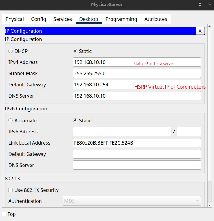
Configuring DHCP and DNS services on the server
DHCP For WiredStaff Vlan 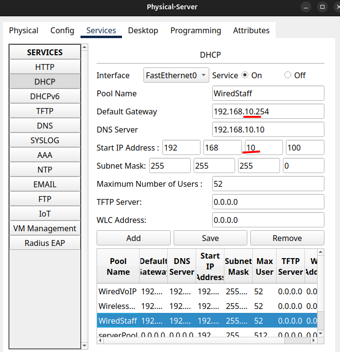
DHCP for WiredVoIP Vlan 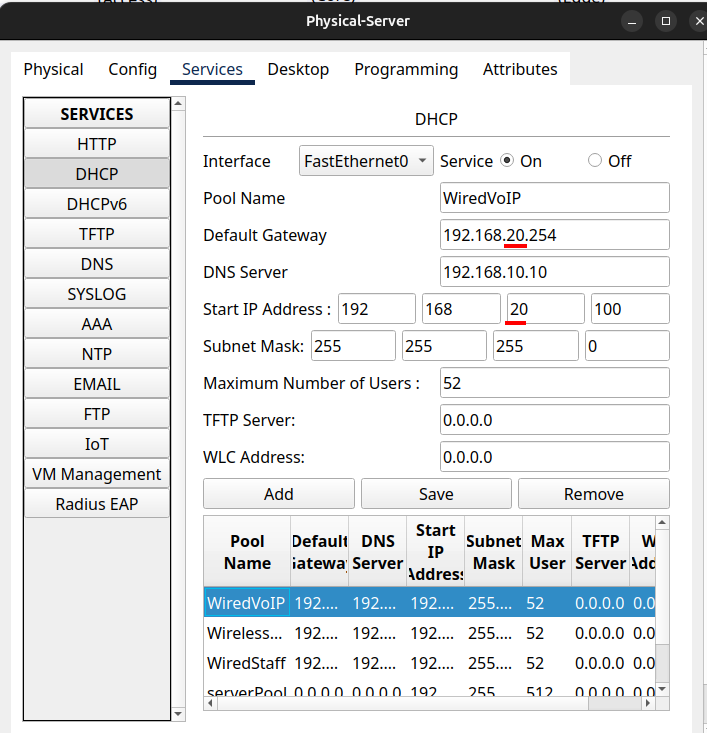
DHCP for WirelessStaff VLAN 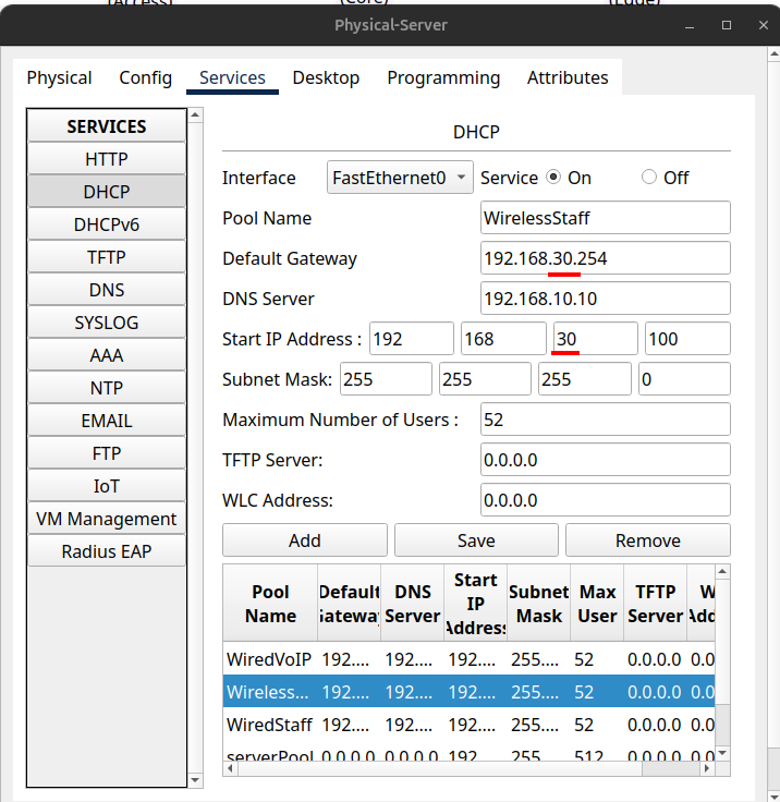
Routing setup
There is full connectivity between the end user devices, to the access and core layer.
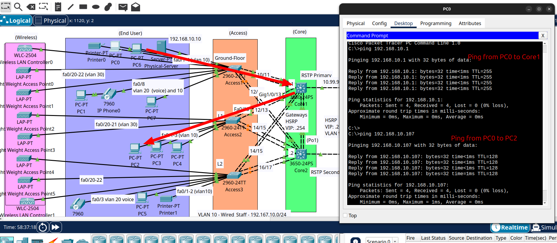
But not connectivity to the external routes on Edges or to the ISPs.
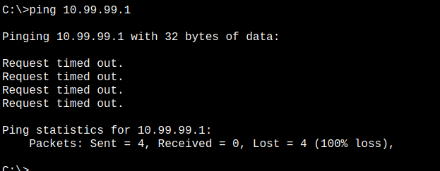
This is because on the Core routers there is no external routes installed
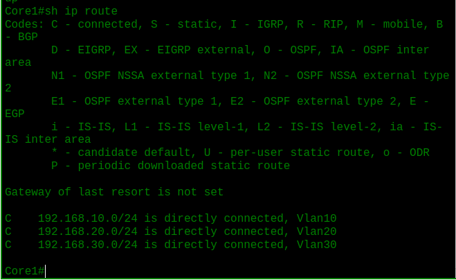
Only routes to the three local LANs.
So now its time to do that connectivity work.
Note: This is usually something that would be handled by a dynamic routing protocol in a larger network, but for the lab I used static and default routes.
I added default routes on the core switches so traffic from the LAN could move toward the edge, using on both: ip route 0.0.0.0 0.0.0.0 10.99.99.254
and I added static routes on the edge routers so return traffic knew how to get back to the internal VLANs, with the following commands: On Edge1:
1
2
3
4
5
6
7
ip route 192.168.10.0 255.255.255.0 10.99.99.201

ip route 192.168.20.0 255.255.255.0 10.99.99.201

ip route 192.168.30.0 255.255.255.0 10.99.99.201

ip route 0.0.0.0 0.0.0.0 GigabitEthernet0/0/0
On Edge2:
1
2
3
4
5
6
7
ip route 192.168.10.0 255.255.255.0 10.99.99.202

ip route 192.168.20.0 255.255.255.0 10.99.99.202

ip route 192.168.30.0 255.255.255.0 10.99.99.202

ip route 0.0.0.0 0.0.0.0 GigabitEthernet0/0/0
I also assigned IP addresses to VLAN 99 on both cores so the default route toward the HSRP virtual IP would actually be reachable.
Core1: 
Core2: 
I wanted the core to send unknown traffic to the edge, and I wanted the edge to know where the internal subnets lived before moving on to NAT. That way, the lab had a complete path in both directions instead of only working one way.
Without those routes, the core only knows its local VLANs and the edge only knows its own uplinks, so traffic stops as soon as it leaves the local segment. Adding the default route and the static routes is what lets the network reach beyond the campus and start talking to the ISP side.
The ping from the PCs are successfull to Edge routers but not to the ISPs 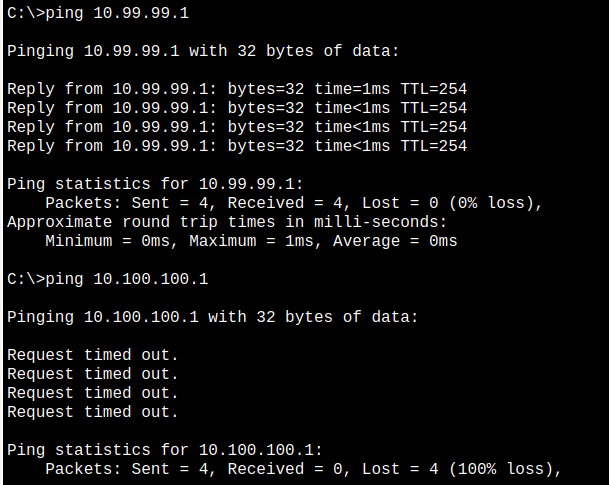
NAT setup
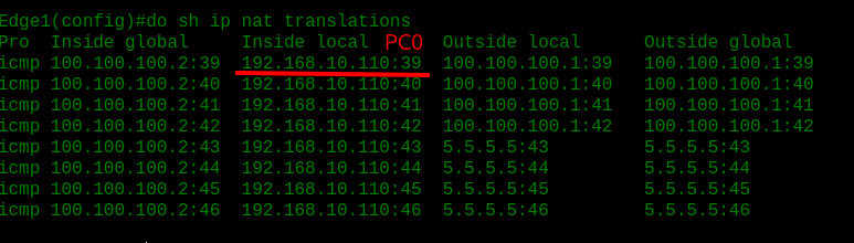
I configured NAT on the edge routers so the internal addresses could be translated to the public-facing addresses before traffic left the network. I used an ACL to match the internal VLAN subnets, marked the WAN side as outside and the LAN side as inside, and then enabled PAT so many internal devices could share the edge router’s public IP.
The idea was to keep all private addressing on the inside of the edge and only expose public IPs on the outside, which is the cleaner real-world design.
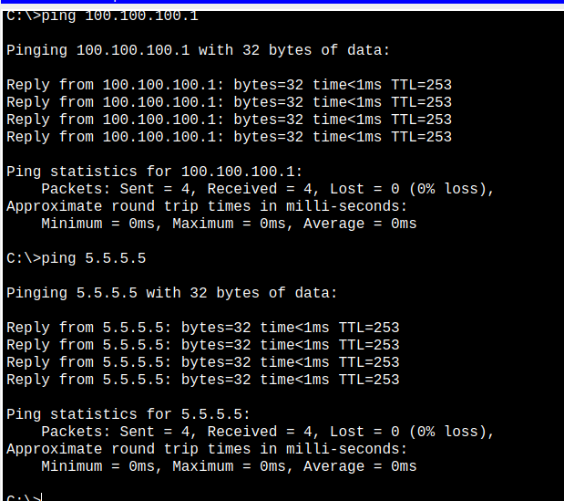
Once NAT was in place, the PCs could finally reach external destinations and even resolve names through DNS. At that point, the lab had a full end-to-end path from the user VLANs out to the internet, which completed the basic redundant design.
Edge1 and Edge2:
1
2
3
4
5
6
7
8
9
10
11
access-list 1 permit 192.168.10.0 0.0.0.255
access-list 1 permit 192.168.20.0 0.0.0.255
access-list 1 permit 192.168.30.0 0.0.0.255
access-list 1 permit 10.99.99.0 0.0.0.255
!
ip nat inside source list 1 interface GigabitEthernet0/0/0 overload
!
interface GigabitEthernet0/0/0
ip nat outside
interface GigabitEthernet0/0/1
ip nat inside
And now we have internet connection: (pinging from PC0)
Testing redundancy
Core failover
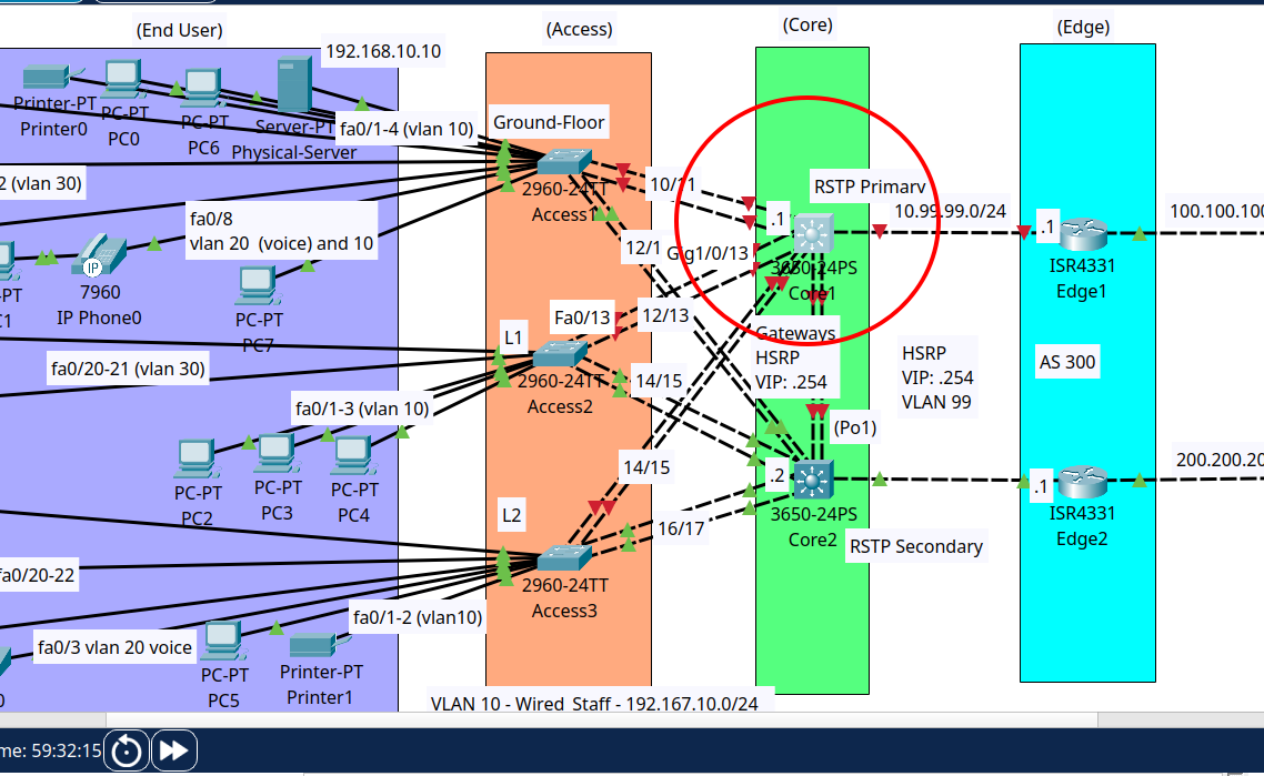
I tested the core redundancy by shutting down core one while a continuous ping was running from the PC. This forced the traffic to fail over to core two, which then became the active path for the network.
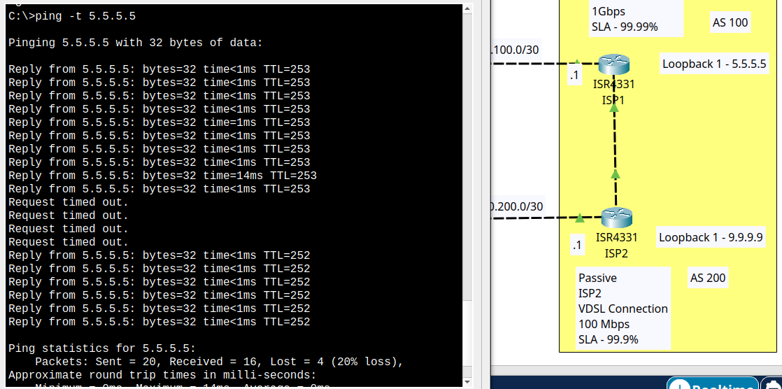
The timeouts come from when I shut down Core1 so all traffic was redirected through Core2
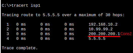
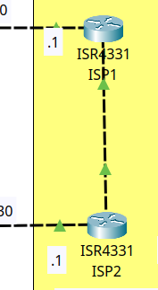
Note: I add to create a new BGP adjacency between ISP1 and ISP2.
Final thoughts
This lab was a strong exercise in understanding how a resilient enterprise network is built from the ground up. It tied together redundancy at every layer, from dual ISPs and edge routers to the core, access, wireless, and end-user devices, which made the overall design much easier to understand in context.
Most importantly, this project was a good reminder that good network design is not just about making connectivity work, but about making it reliable, scalable, and maintainable. I used this lab as a guided learning experience, and it helped strengthen both my practical skills and my understanding of how layered redundancy is built into real networks.