From Fundamentals to Enterprise Complexity
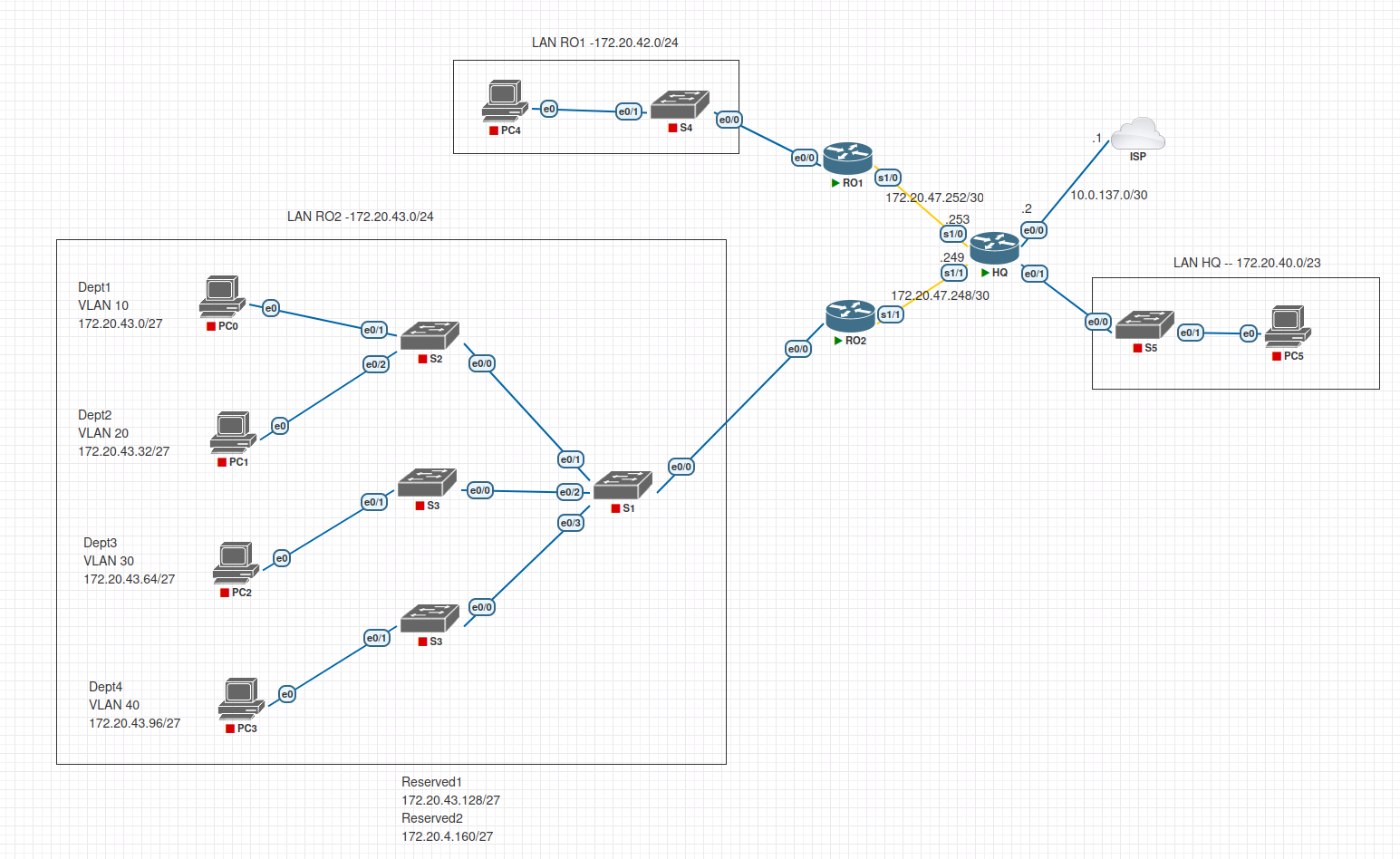
Project Idea: From Fundamentals to Enterprise Complexity
The philosophy behind this project is continuous, iterative improvement. Instead of building isolated labs every week, I am developing a single, “living” topology that evolves as I master new technologies.
At its inception, the design focuses on core foundational services: VLANs, DHCP relay, Router on a Stick implementation, Multi-Area OSPF, and NAT. While the initial setup may seem simple, the goal is to move this network through the full “Day 0 to Day N” lifecycle, systematically making it more efficient, redundant, and secure.
On the side, I perform intensive troubleshooting exercises that I don’t always share in my portfolio. However, I use the lessons from those “breaks” to harden this main project, intentionally adding complexity and resolving the types of real-world issues, like configuration drift and protocol mismatches, that network engineers face daily. This blog serves as a record of that growth.
The Real-World Scenario: Enterprise Branch Expansion
In a professional environment, this project represents a typical branch expansion. I am simulating the integration of a new site, Remote Office 2 (RO2), into a corporate infrastructure that already supports a Main Site (500 employees) and Remote Office 1 (220 employees).
The Project Brief
My objective is to build the RO2 network from the ground up to support four initial departments. Each department requires its own dedicated subnet to maintain separate broadcast domains. To ensure high availability and hardware efficiency, I am distributing users from all four departments across a four-switch fabric. Furthermore, I am designing the IP plan to accommodate two additional departments for future recruitment, totaling six subnets.
I have structured this project into three distinct phases:
- Phase 1: VLSM Address Scheme – I will use Variable Length Subnet Masking (VLSM) to subdivide a single
/24block into smaller, efficient subnets that meet the specific host counts for each department without wasting address space. - Phase 2: Network Setup and Basic Configuration – I will perform the physical-to-logical mapping, configure secure management access (SSH), and set up the switch infrastructure, including VLANs and trunking.
- Phase 3: OSPF Routing and Internet Access – I will implement Multi-Area OSPF to provide dynamic, loop-free reachability between the Main Site, RO1, and RO2, while configuring NAT to allow RO2 users to access the Internet.
Defining IP Addresses and Subnets
Addressing Table
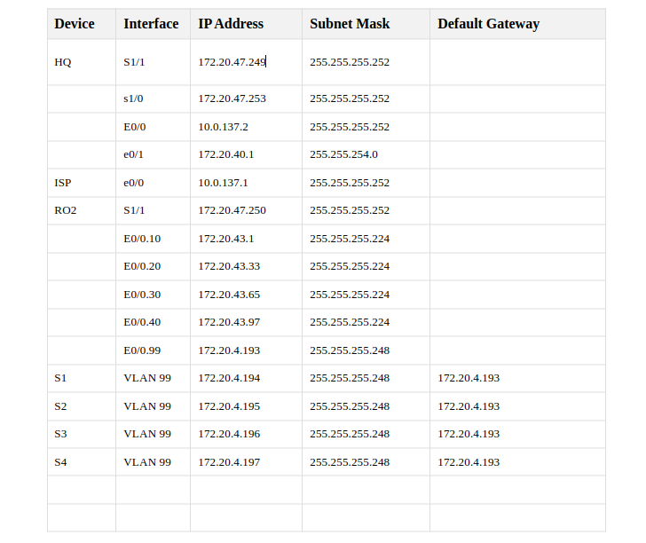
To support 180 employees across 6 departments in RO2 (30 users per department), I will subdivide the 172.20.43.0/24 block using VLSM, I will use a /27 mask for departments, providing 30 usable host addresses per subnet (25−2=30), and a more efficient /29 mask for management.
RO2 Subnet Design (172.20.43.0/24)
| Department | Subnet ID | Mask | Usable Host Range | Broadcast |
|---|---|---|---|---|
| Dept 1 | 172.20.43.0 | /27 | 172.20.43.1 - .30 | 172.20.43.31 |
| Dept 2 | 172.20.43.32 | /27 | 172.20.43.33 - .62 | 172.20.43.63 |
| Dept 3 | 172.20.43.64 | /27 | 172.20.43.65 - .94 | 172.20.43.95 |
| Dept 4 | 172.20.43.96 | /27 | 172.20.43.97 - .126 | 172.20.43.127 |
| Reserve 1 | 172.20.43.128 | /27 | 172.20.43.129 - .158 | 172.20.43.159 |
| Reserve 2 | 172.20.43.160 | /27 | 172.20.43.161 - .190 | 172.20.43.191 |
| Management | 172.20.43.192 | /29 | 172.20.43.193 - .198 | 172.20.43.199 |
This plan leaves 172.20.43.200 through 172.20.43.255 unused for future expansion.
Topology and Secure Remote Access
I connected the devices as required, 4 departments on RO2, dividing the RO2 LAN into 6 subnets, not done any configuration yet.
With the topology physically connected, I must now configure secure management. Remote access via SSH is preferred over Telnet because it encrypts all traffic, including passwords.
Router Configuration (RO2 example)
1
2
3
4
5
6
7
8
9
10
11
12
hostname RO2
enable secret cisco123
!
ip domain-name case.study
crypto key generate rsa modulus 2048
ip ssh version 2
!
username admin secret cisco123
!
line vty 0 4
 login local
 transport input ssh
Switch Configuration (S1 example)
The switch requires a Switched Virtual Interface (SVI) for management and a default gateway to reach the HQ and RO1 networks
1
2
3
4
5
6
7
8
9
10
11
12
13
14
15
16
17
18
19
20
hostname S1
enable secret cisco123
!
ip domain-name case.study
crypto key generate rsa modulus 2048
username admin secret cisco123
!
vlan 99
 name Management
!
interface vlan 99
 ip address 172.20.43.194 255.255.255.248
 no shutdown
!
! Gateway must be the RO2 subinterface for VLAN 99
ip default-gateway 172.20.43.193
!
line vty 0 15
 login local
 transport input ssh
I did this configuration for all routers and switchtes so all are possible to access remotely.
DHCP
On HQ I create a pool for each VLAN on RO2 LAN. I excluded RO2 and Switches VLAN interfaces (used for remote login), which I will change to a new vlan for management, which i forgot to create before.
The only devices that dont receive dynamic IP addresses are the switches. They receive the following static IP addresses. S1: 172.20.43.194 S2: 172.20.43.195 S3: 172.20.43.196 S4: 172.20.43.197
1
2
3
4
5
6
7
8
9
10
11
12
13
14
15
16
17
18
19
20
21
22
23
24
25
26
HQ Router

ip dhcp excluded-address 172.20.43.1  ! RO2's subinterface e0/0.10 IP
ip dhcp pool RO2_VLAN10
network 172.20.43.0 255.255.255.224
default-router 172.20.43.1
dns-server 8.8.8.8

ip dhcp excluded-address 172.20.43.33  ! RO2's subinterface e0/0.20 IP
ip dhcp pool RO2_VLAN20
network 172.20.43.32 255.255.255.224
default-router 172.20.43.33
dns-server 8.8.8.8


ip dhcp excluded-address 172.20.43.65  ! RO2's subinterface e0/0.30 IP
ip dhcp pool RO2_VLAN30
network 172.20.43.64 255.255.255.224
default-router 172.20.43.65
dns-server 8.8.8.8

ip dhcp excluded-address 172.20.43.97  ! RO2's subinterface e0/0.40 IP
ip dhcp pool RO2_VLAN40
network 172.20.43.96 255.255.255.224
default-router 172.20.43.97
dns-server 8.8.8.8
and on RO2
1
2
3
4
5
6
7
8
interface e0/0.10
ip helper-address 172.20.47.249 ! HQ IP s1/1 IP address
interface e0/0.20
ip helper-address 172.20.47.249
interface e0/0.30
ip helper-address 172.20.47.249
interface e0/0.40
ip helper-address 172.20.47.249
DHCP Implementation
I am using a centralized DHCP model where HQ acts as the server and RO2 acts as the relay agent. This allows for easier management of all IP leases from a single device. Later I am planning to implement it through a windows server.
HQ DHCP Server Configuration
I created a dedicated pool for each user VLAN. I excluded the gateway IP address (RO2’s subinterface IP) for each pool to prevent the server from assigning it to a PC, which would cause an IP conflict.
1
2
3
4
5
6
7
8
9
10
11
12
13
14
15
16
17
18
19
20
21
22
23
24
25
26
! --- Global Exclusions ---
ip dhcp excluded-address 172.20.43.1   ! VLAN 10 Gateway
ip dhcp excluded-address 172.20.43.33  ! VLAN 20 Gateway
ip dhcp excluded-address 172.20.43.65  ! VLAN 30 Gateway
ip dhcp excluded-address 172.20.43.97  ! VLAN 40 Gateway

! --- DHCP Pools ---
ip dhcp pool RO2_VLAN10
 network 172.20.43.0 255.255.255.224
 default-router 172.20.43.1
 dns-server 8.8.8.8

ip dhcp pool RO2_VLAN20
 network 172.20.43.32 255.255.255.224
 default-router 172.20.43.33
 dns-server 8.8.8.8

ip dhcp pool RO2_VLAN30
 network 172.20.43.64 255.255.255.224
 default-router 172.20.43.65
 dns-server 8.8.8.8

ip dhcp pool RO2_VLAN40
 network 172.20.43.96 255.255.255.224
 default-router 172.20.43.97
 dns-server 8.8.8.8
RO2 DHCP Relay Configuration
Since DHCP Discover messages are broadcasts, they cannot cross the WAN to reach HQ by default. To fix this, I configured the ip helper-address on RO2’s subinterfaces. This tells RO2 to listen for client broadcasts and forward them as unicast packets to the HQ server at 172.20.47.249.
1
2
3
4
5
6
7
8
9
10
11
interface Ethernet0/0.10
 ip helper-address 172.20.47.249
!
interface Ethernet0/0.20
 ip helper-address 172.20.47.249
!
interface Ethernet0/0.30
 ip helper-address 172.20.47.249
!
interface Ethernet0/0.40
 ip helper-address 172.20.47.249
Router-on-a-Stick (ROAS) Implementation
Now that the DHCP server is ready, I must configure the path between the clients and the router. I am using Router-on-a-Stick (ROAS), which uses a single physical link to carry multiple VLANs between the switches and the router RO2.
Switch Access and Trunk Ports
First, I configured the access ports for the end-user devices and the trunk links to interconnect the switches. I changed the Native VLAN to 999 on all trunks as a security best practice to ensure untagged traffic is isolated.
Example: Switch S2 (Departments 1 & 2)
1
2
3
4
5
6
7
8
9
10
11
12
13
14
15
16
interface Ethernet0/1
 description Dept_1_Access
 switchport mode access
 switchport access vlan 10
!
interface Ethernet0/2
 description Dept_2_Access
 switchport mode access
 switchport access vlan 20
!
interface Ethernet0/0
 description Trunk_to_S1
 switchport trunk encapsulation dot1q
 switchport mode trunk
 switchport trunk native vlan 999
 switchport trunk allowed vlan 10,20,99,999
Example: Switch S1 (The “Core” Switch)
S1 aggregates all traffic from S2, S3, and S4 and sends it to the router. It must allow all department VLANs and the management VLAN.
1
2
3
4
5
6
interface Ethernet0/0
 description Trunk_to_RO2
 switchport trunk encapsulation dot1q
 switchport mode trunk
 switchport trunk native vlan 999
 switchport trunk allowed vlan 10,20,30,40,99,999
Router RO2 Configuration
I created logical subinterfaces on RO2’s physical port to act as the default gateway for each VLAN. Each subinterface must match the VLAN ID used on the switches.
1
2
3
4
5
6
7
8
9
10
11
interface Ethernet0/0.10
 encapsulation dot1q 10
 ip address 172.20.43.1 255.255.255.224
!
interface Ethernet0/0.99
 encapsulation dot1q 99
 ip address 172.20.43.193 255.255.255.248
!
interface Ethernet0/0.999
 description Native_VLAN_Security
 encapsulation dot1q 999 native
Note: I ensured that every VLAN (10, 20, 30, 40, 99, 999) was manually created in the VLAN database of every switch. If a switch does not “know” a VLAN exists, it will discard all traffic for that ID, even if the trunk is configured to allow it
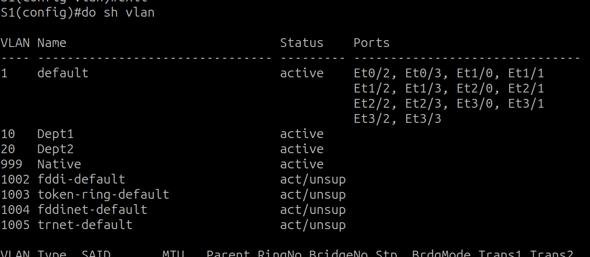
To act as the default gateway for my four departments, I configured Logical Subinterfaces on RO2’s physical interface. Each subinterface uses 802.1Q encapsulation to “peel off” the tags from incoming switch frames.
RO2 Configuration
1
2
3
4
5
6
7
8
9
10
11
12
13
14
15
16
17
18
interface GigabitEthernet 0/0
 no shutdown
!
interface GigabitEthernet 0/0.10
 encapsulation dot1q 10
 ip address 172.20.43.1 255.255.255.224
!
interface GigabitEthernet 0/0.20
 encapsulation dot1q 20
 ip address 172.20.43.33 255.255.255.224
!
interface GigabitEthernet 0/0.30
 encapsulation dot1q 30
 ip address 172.20.43.65 255.255.255.224
!
interface GigabitEthernet 0/0.40
 encapsulation dot1q 40
 ip address 172.20.43.97 255.255.255.224
Troubleshooting the “Missing VLAN” Issue
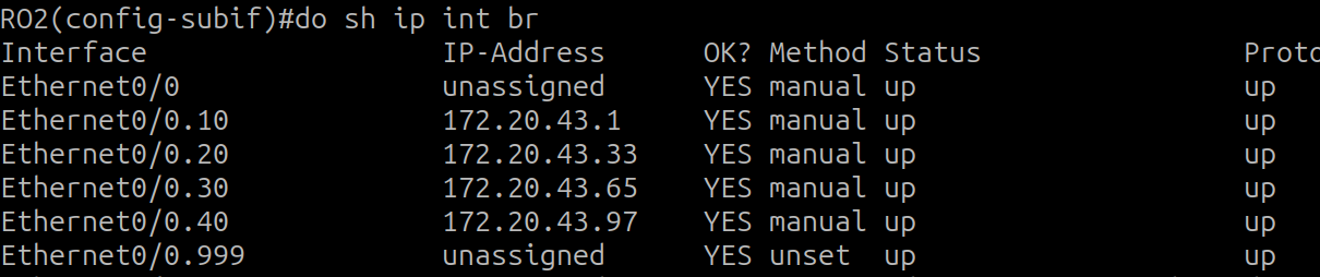
I ping from PC0 (vlan 10) to RO2. First pings where not working because although I configurated the trunks properly on S1 e0/1 and e0/0, i forgot to create the VLANs , so they were not appearing when doing show vlan. After creating them, it worked fine.
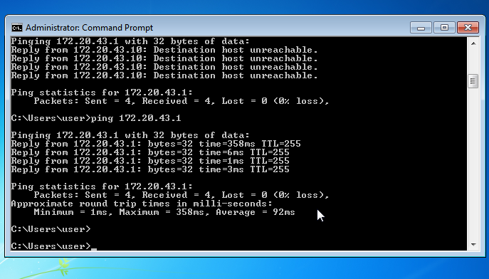
When I first attempted to connect VLAN 30 from S3, the ping to the router failed.
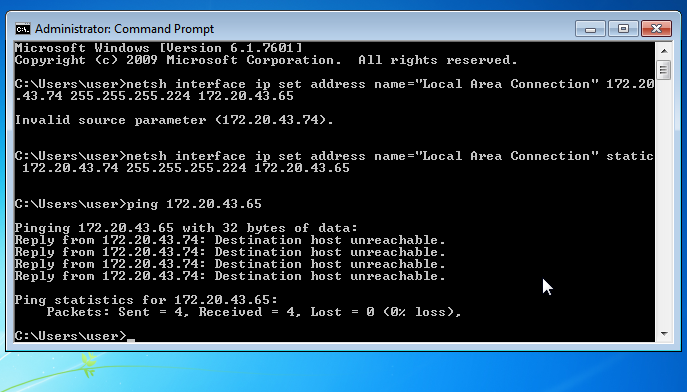
Using show vlan and show interfaces trunk, I identified two problems:
- The native VLAN on S3 was still the default (VLAN 1), while the core switch (S1) was using VLAN 999.
- Interface E0/0 was not yet operating as a trunk
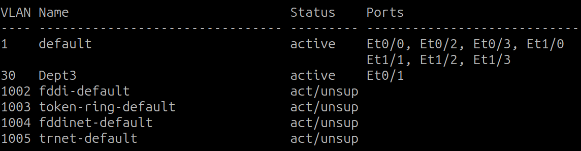

sh vlan shows me two things, first that the native vlan continues being 1 which has to be changed to 999, and that e0/0 is not configured as a trunk yet, and thats why the traffic from vlan 30 is not being carried.
I corrected this by explicitly defining the trunk and native VLAN:
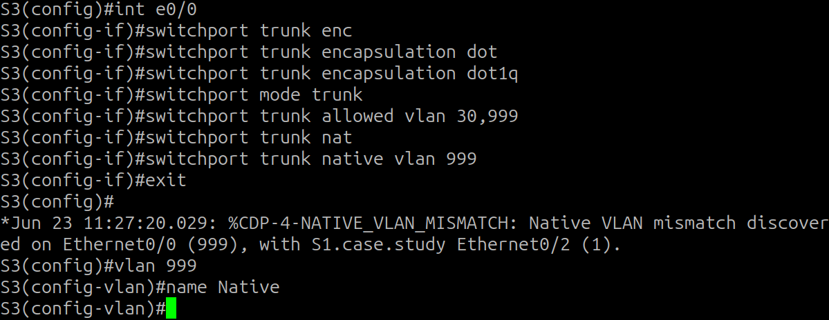
so now the trunk has been created
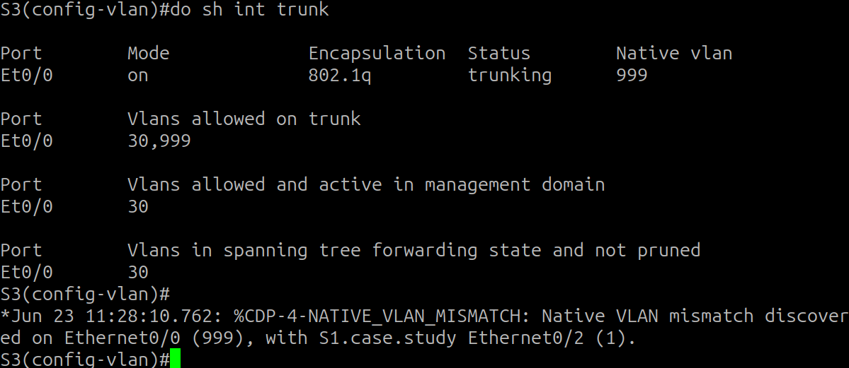
and I will fix the mismatch chaging the S1 e0/2 configuration now
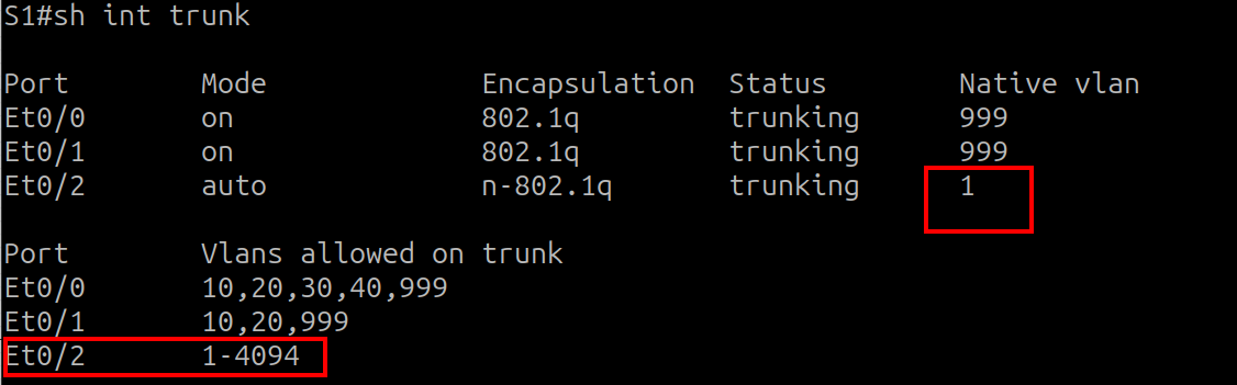
here we can see that the native vlan is mismatched and that the VLANs allowed where not specified yet. So i do both
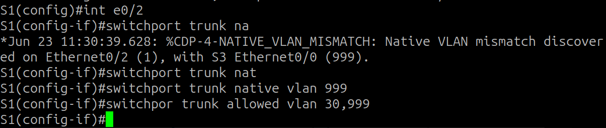
but ping to the router from the PC still doesnt work. Why?
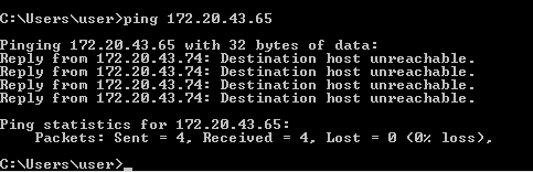
Simply because the VLAN 30 on S1 hasnt been created yet.
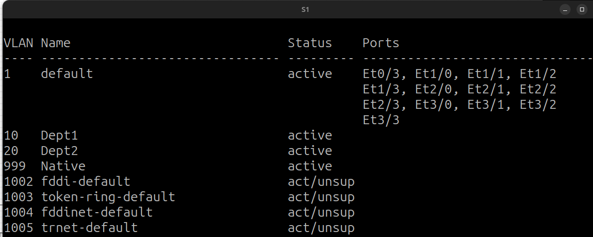
I create it
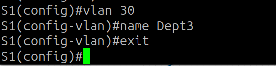
And the ping works.
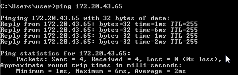
I take this: create first the vlans on all devices that are going to transmit them so I dont find this silly mistake again.
So, in S3 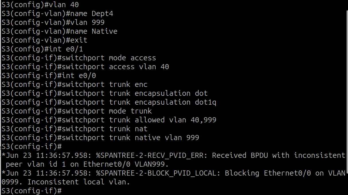
Those errors are fixed configurating S1 e0/3 properly 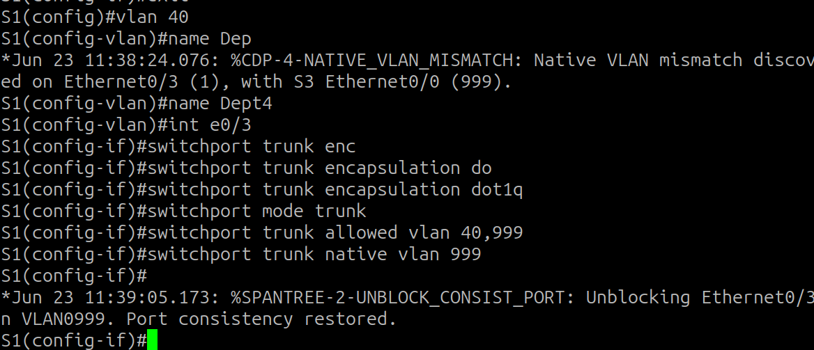
and PC3 from VLAN 40 pings easily to its router (RO2) 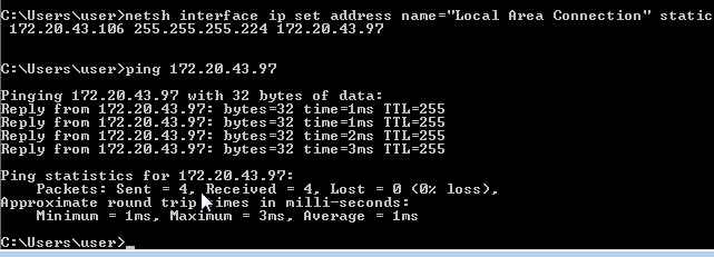
To verify that my Router-on-a-Stick (ROAS) configuration was fully functional, I performed an internal inter-VLAN test by pinging from Dept 1 (VLAN 10) to Dept 4 (VLAN 40).
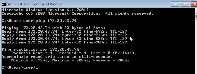
The ping was successful, confirming that:
- The PCs are correctly receiving IP addresses via DHCP relay.
- The switches are tagging frames with the correct 802.1Q headers.
- RO2 is successfully routing traffic between its logical subinterfaces.
OSPF Area Design and Communication
To enable communication between RO1, HQ, and RO2, I implemented Multi-Area OSPF. This allows for a hierarchical design where Area 0 acts as the backbone connecting the remote sites.
OSPF Design Strategy
- Router IDs (RID): On each router, I created a Loopback 0 interface to serve as the RID. Since loopbacks are virtual, they remain “up/up” as long as the router is powered on, ensuring the OSPF process remains stable.
- Configuration Style: While I used the traditional
networkcommand on RO1, I used the modern best practice of interface-level OSPF configuration for the other routers to ensure precision
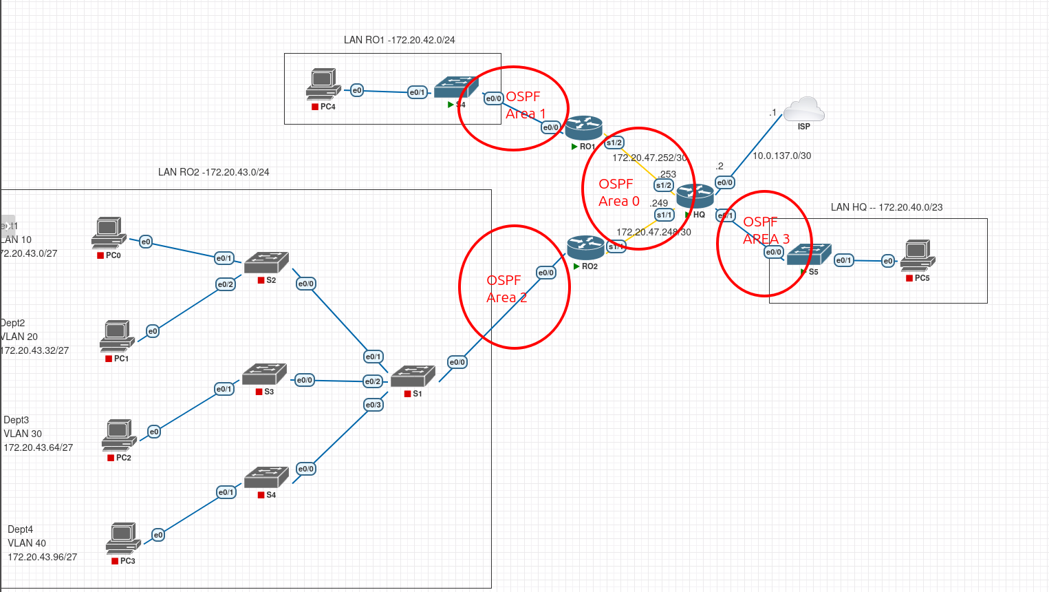
RO1 (I will only use the network command on RO1, on the other routers I will use what is best practice, assigning it directly to the interface) 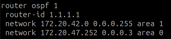
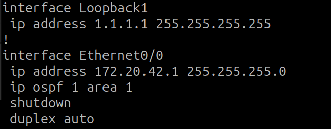
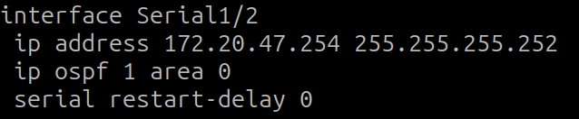
HQ Configuration
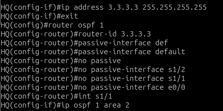 (mistake, s1/1 should be in area 0, corrected below)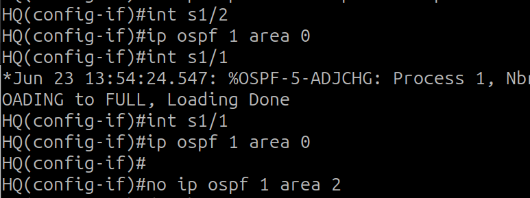
- Passive-Interface Default: I silenced OSPF on all interfaces by default. I then manually re-enabled it only on the WAN links. This prevents the router from sending unnecessary “Hello” packets onto user LANs, which saves CPU and prevents potential attackers from learning the topology.
- Point-to-Point Network Type: On the Serial and direct Ethernet WAN links, I forced the network type to
point-to-point. This tells OSPF that only two routers exist on the link, allowing it to bypass the Designated Router (DR) election and the associated 40-second wait timer.
with both ospf processes running on RO1 and HQ I check if they are learning each other networks, which they do. HQ learns LAN RO1 network: 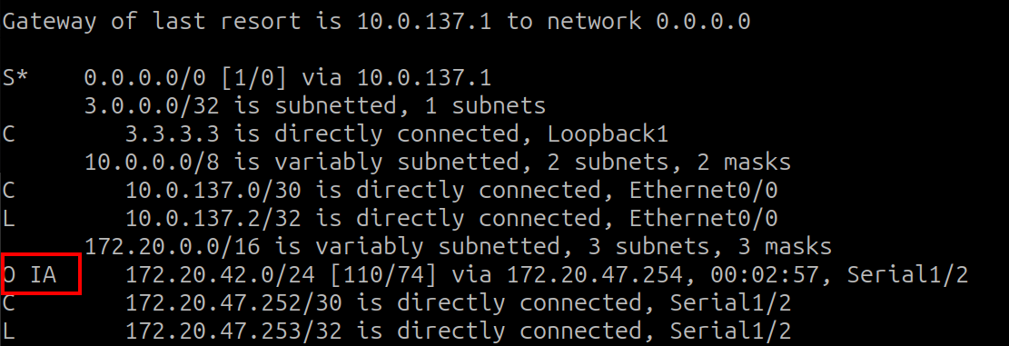
but RO1 is not learning LAN HQ network: 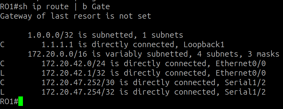
I ask myself why, adjacency is alright 
but HQ shows me that the state of the protocol is down, why? 
and with show ip interface brief I can see two hints 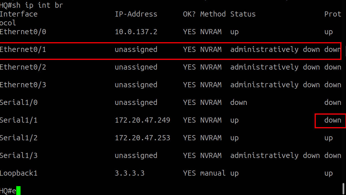
The first one is that the interface connecting the LAN doesnt have an IP address configured, for a configuration later the interface to RO2 is down, so I will keep that in mind. So I will start fixing what has to do with e0/1

The subnet mask is /23 so it is 255.255.254.0. Right after that I can see that the protocol goes up

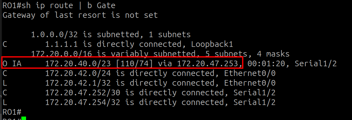
and the route to LAN HQ is advertised now from HQ to RO1 through OSPF.
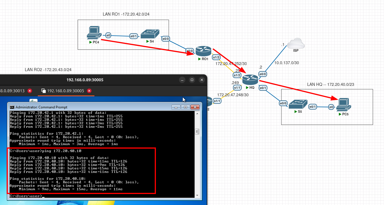
To test it I make a ping from PC4 on RO1 to PC5 on LAN HQ, which is successfull.
I will continue configuring the connectivity to RO2 LAN, configuring OSPF on its router.
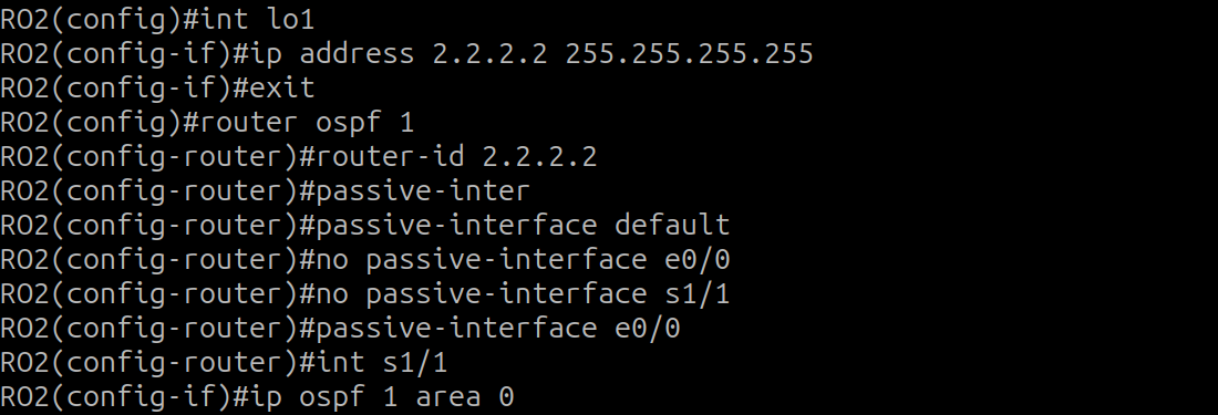
e0/0 will be passive to avoid sending hello packets as there is no network, and prevents unautorized routers to form an adjacency.
I can see the adjacency forming and after that the routes being advertised to RO2 from HQ using OSPF
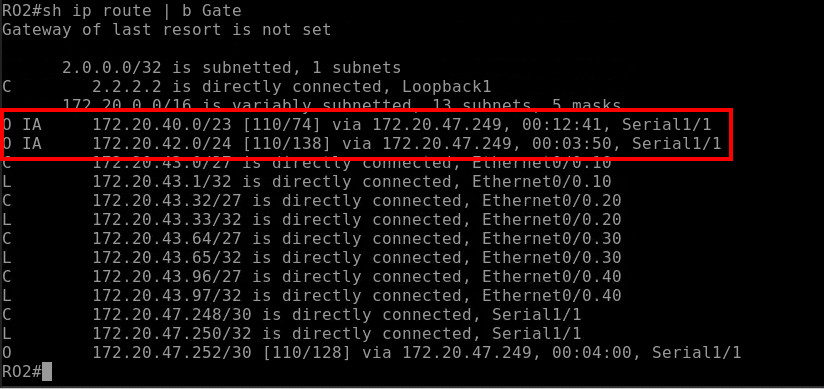
As I have implemented ROAS and I dont have an IP address directly on RO2 e0/0 but only on its subinterfaces, I find it easier to use the network command in this case to advertise RO2 LAN.

and after that i check that this routes are being learned by HQ Router
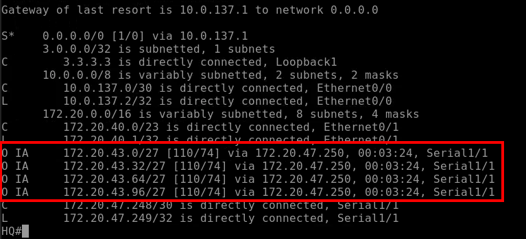
and I will now configure HQ to advertise its default route to its neighbors, with default-information originate and I can see it afterwards on RO1 and RO2

But even though I have the route I can not ping external networks from the ISP

Why? Well, I haven’t configure NAT overload on my HQ router, so the ISP does not have a route to the internal network
NAT Overload configuration
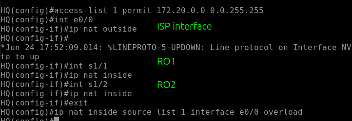
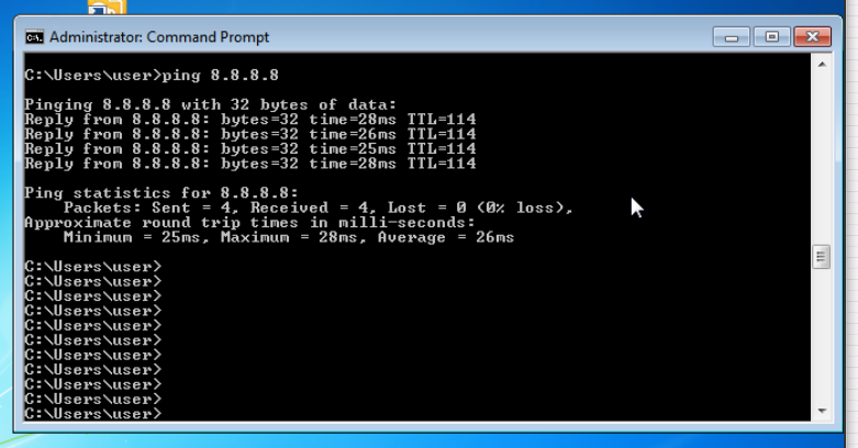
and after doing that, now a ping to 8.8.8.8 (google dns) works from PC
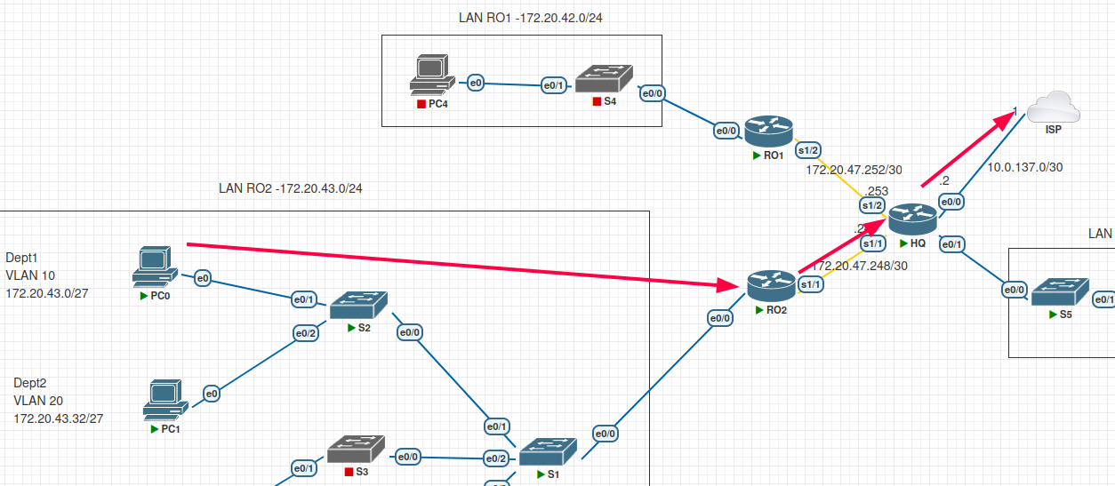
sh ip nat translations on HQ router shows me the work being done by HQ now

Inside global: “Public” IP address of my HQ router that the internet sees as the source of the traffic Inside local: actual private IP address of the host (in this case PC0 on LAN RO2) Outside global: Public IP address of the destination server, in this case Google DNS. Outside Local: In standard source NAT this is typically identical to the outside global address
Summary
With the successful implementation of Multi-Area OSPF, Remote Office 2 is now fully integrated into the corporate backbone. By following a structured approach—starting with a rigid VLSM design and moving through Layer 2 segmentation to Layer 3 dynamic routing—I have established a stable, reachable network environment
Summary of Accomplishments:
- Logical Segmentation: Successfully implemented ROAS and trunking, ensuring that four distinct departments are isolated at Layer 2 but can communicate through the RO2 gateway.
- Automated Services: Configured HQ as a centralized DHCP server, with RO2 acting as a relay agent to provide efficient IP addressing across all user subnets.
- Dynamic Reachability: Established Multi-Area OSPF adjacencies using stable Loopback RIDs and optimized point-to-point network types for fast convergence